


 中文
中文


Ten layer HDI (1st, 2nd, 3rd, 4th, arbitrary order) stacked impedance PCB design techniques
Time: 2023-11-07 09:30:30
Click:
Introduction: This article will provide a detailed introduction to the PCB design techniques for ten layer HDI (1st, 2nd, 3rd, 4th, any order) stacked impedance. By reading this article, you will learn how to effectively design and optimize your PCB layout to improve product performance and reliability.
Introduction: This article will provide a detailed introduction to the PCB design techniques for ten layer HDI (1st, 2nd, 3rd, 4th, any order) stacked impedance. By reading this article, you will learn how to effectively design and optimize your PCB layout to improve product performance and reliability.
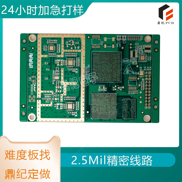
HDI (High Density Interconnector) is a high-density interconnect technology that enables more circuit connections within a limited space. Ten layer HDI (1st, 2nd, 3rd, 4th, arbitrary order) stacked impedance is a special HDI technology that can provide higher signal transmission rates and lower signal losses.
In PCB design, stack impedance is a very important parameter. It directly affects the quality of signal transmission. Therefore, when designing a ten layer HDI (1st, 2nd, 3rd, 4th, any order) stacked impedance, certain specific design techniques need to be followed.
Firstly, we need to choose suitable materials. Generally speaking, using materials with low dielectric constants can reduce the impedance of the stack. In addition, we also need to consider factors such as material thickness and thermal expansion coefficient.
Secondly, we need to layout the copper foil reasonably. During the design process, efforts should be made to avoid situations where the copper foil is too long or too short. In addition, attention should be paid to the spacing between copper foils to ensure the stability of signal transmission.
Thirdly, we need to control the direction of the line. During the design process, efforts should be made to avoid excessively winding or intersecting lines. In addition, attention should be paid to the distance between the lines to prevent signal interference.

Address: Room 605, Building B, Bay Area Artificial Intelligence Industrial Park, Huanggangling Industrial Zone, Xixiang, Bao'an District, Shenzhen
Phone: 18025855806
Fax: 0755-27583285
Email:sd@dj-pcb.com
CopyRight © Shenzhen Dingji Electronics Co., Ltd. 粤ICP备16081348号 SITEMAP
Website Design:Yaqun Network
版权所有:深圳鼎纪电子有限公司
 QQ客服
QQ客服